ACQ - Configuration
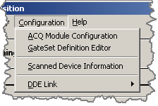
The ACQ Program Configuration Menu:
         The 'Execute Advisory' submenu items each have an
      advisory code number.  An external program can control
      the acquisition process by using the Dynamic Data Exchange
      protocol (DDE).  The commands are of the form:

               Advisory = #

      where # is any valid advisory code number.  The DDE link
      topic is AcqF.

		   More information about the DDE option can be found
      in the configuration of the DDE Link section.

ACQ Module Configuration
         Clicking on the 'ACQ Module Configuration' menu item
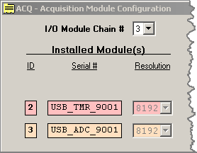
      opens the 'Acquisition Module Configuration' window:

         The configuration window is used to set various module
      parameters and enable/disable any of the attached USB ADC
      or USB TMR modules.  The configuration sections are:
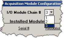
IO Module Chain
         The IO Module Chain dropdown box selects a 'chain' of
      IO modules (see the section describing IO Modules) to be
      presented on the configuration window:
Installed Modules
         Each row of the Acquisition Module Configuration window
      corresponds to an IO Module belonging to the selected
      'Chain'.

      The 'Installed Module(s)' section contains:

      ID            - The IO Module's hardware id number
      Serial Number - The IO Module's serial number
      Resolution    - The IO Module's display resolution
      The 'Resolution' dropdown box selects the number of data
      channels the raw 8192 channel acquisition data is binned
      into.
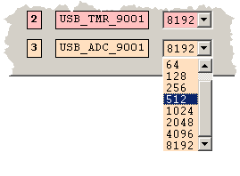
      If a resolution of 512 is selected then the raw
      ADC data is rebinned so that every 8 channels of the 8192
      channel data is combined into 1 channel in the 512 channel
      spectrum.
Module Control
      The 'Module Control' section contains:

      Timer Interval - The timimg interval selection (Timers Only)
      MP             - Select Multi-Parameter mode
      Enable         - Enable/Disable the IO Module
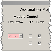
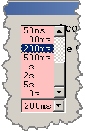
         The 'Timer Interval' dropdown selection box is only available
      when the IO Module is detected as a timer.  The timer intervals
      are 100, 200, and 500 microseconds, 1, 2, 5, 10, 20, 50, 100,
      200, and 500 milliseconds, and 1, 2, 5, and 10 seconds.
         A timer module is used when multi-channel scaling
      acquisition is required.  Typically a TMR and ADC IO Module
      are paired together in a 'Chain' and multi-parameter acquisition is
      enabled to create a multi-channel scaling configuration.

         The 'MP' check box selects multi-parameter data acquisition
      rather than single channel acquisition.

         The 'Enable' check box must be checked to activate the
      IO Module for data acquisition.  An unchecked box disables
      this IO Module.
Module Status
      The 'Module Status' section contains:

      Events/Sec.  - The counting rate in events/second
      Event Errors - The number of data transfer errors

         The 'Events/Sec.' box gives an approximate count rate
      for the IO Module.  In multi-parameter acquisition all 'MP'
      enabled IO modules in the selected chain will show the same
      count rate as each 'data event' contains data from every 'MP'
      enabled channel.

         The 'Event Errors' indicate the number of data
      transfer errors encountered during the whole of the
      acquisition time for the IO Module.  Note that during
      multi-parameter acquisition all data is transfered through
      the lowest ID module in the chain and errors are reported
      only in the lowest ID channel.  Typical error rates are
      less then 1 per 10^8 events.

GateSet Definition Editor
         The editor provides a method to create spectra based
      on any or all of the parameters in a chain acquired in
      in multi-parameter mode.  Parameters may be bound by
      low and high limits specified by value or lower and upper
      cursor levels selected during acquisition.

         Clicking on the 'GateSet Definition Editor' menu item
      displays the GateSet Definition Editor.
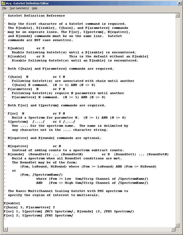
	   A typical default GateSet definition file is shown.  This
      text file contains a summary of the commands recognized by
      the Gating Set Processor of the ACQ program.  The text
      editting window supports the common edit commands CTRL C,
      CTRL V, and CTRL X plus text selection via the SHIFT and
      arrow keys or mouse.

         A summary of the gateset commands is shown at the beginning
      of the currently loaded gateset definition file.  What follows
      is a slightly expanded explanation of the commands.


      Only the first character of a GateSet command is required.
      The Enable, Disable, Chain, and Parameters commands may be
      placed on seperate lines.  The For, Spectrum, Negative,
      and Bounds commands must be on the same line.  GateSet
      commands are NOT case sensitive and may be abbreviated
      to just the first character of the command.

         E[nable] or E
            Enable the following GateSet(s) until a
            D[isable] is encountered.

         D[isable] or D
            This is the default without an E[nable].
            Disable following GateSet(s) until an
            E[nable] is encountered.

      The C[hain] and P[arameter] commands are
      required before the spectrum building commands.

         C[hain] N    or    C N
            Following GateSet(s) are associated with
            the specified chain until another C[hain]
            command.  (N >= 1) AND (N <= 8)

         P[arameter] N    or    P N
            Where the number of parameters in the associated
            IO chain is (N >= 1) AND (N <= 8).  The
            following GateSet(s) are associated with
            the specified parameter count until another
            P[arameter] command.

      The number N in the following command definitions
      refer to Nth parameter in the current IO chain and
      not to the device ID of the IO module.

      The F[or] and S[pectrum] commands are required
      in the gateset definition.  N[egative] and B[ounds]
      commands are optional.

         F[or] N    or    F N
            Build a Spectrum from the Nth parameter
            specified in the current IO chain.
            Where (N >= 1) AND (N <= parameter count).

         S[pectrum] /..../    or    S /..../
            This command specifies the name of the spectrum
            which will be displayed in the ACQ spectrum selection
            dropdown box.  The .... is used for the spectrum
            name.  The name is delimited by any character not
            in the .... character string.

         Negative    or    N
            Instead of adding counts to a spectrum counts
            are subtracted.

         B[ounds]  (BoundSet1) ... (BoundSetN)
         or     B  (BoundSet1) ... (BoundSetN)
            Build a spectrum when all BoundSet conditions are met.
            The BoundSet may be of the form:
               (N, LoBound, HiBound) where the value of
               parameter N, NVal, must meet the conditions
               (NVal >= LoBound) AND (NVal <= HiBound)
            or
               (N, /SpectrumName/)  where the value of
               parameter N, NVal, must meet the conditions
               (NVal >= Low  Sum/Strip Channel of /SpectrumName/)  AND
               (NVal <= High Sum/Strip Channel of /SpectrumName/)


      The default GateSet file contains the following
      gateset commands:

         ' The Basic MultiChannel Scaling GateSet with PHS spectrum to
         ' specify the region of interest to multiscale.

         E[nable]
         C[hain] 3, P[arameters] 2
         F[or] 1, S[pectrum] /MCS Spectrum/, B[ounds] (2, /PHS Spectrum/)
         F[or] 2, S[pectrum] /PHS Spectrum/

      This basic gateset contains all the necessary elements to
      create two spectra: an MCS Spectrum (multi-channel scaling)
      and a PHS Spectrum (normal pulse-height spectrum).

      E[nable] enables the following command lines.  The C[hain]
      and P[arameter] elements specify chain number 3 having two
      parameters.  The two following command lines each create a
      spectra.  The first spectrum created is the /MCS Spectrum/
      which is built from parameter 1 (a TMR module) with a bounds
      specification for the second parameter (an ADC module).
      The upper and lower bounds are from the upper and lower
      cursor set points from spectrum /PHS Spectrum/.  The
      second spectrum created is the /PHS Spectrum/ which is built
      from parameter 2 (the ADC module).  Note that this spectrum
      /PHS Spectrum/, is the spectrum used for the bounds in
      spectrum 1 (/MCS Spectrum/).

      This gateset is useful for measuring the radioactive decay of
      nuclear isotopes.  The upper and lower bounds select a
      particular radioactive decay from the /PHS Spectrum/ and
      an acquisition time interval is selected for the TMR IO Module.
      The TMR and ADC are enabled and set for multi-parameter
      acquisition.  The acquired /MCS Spectrum/ will contain a time
      history of the radioactive decay and can be used to easily
      find the decay halflife.
GateSet Definition Editor Menu
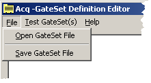
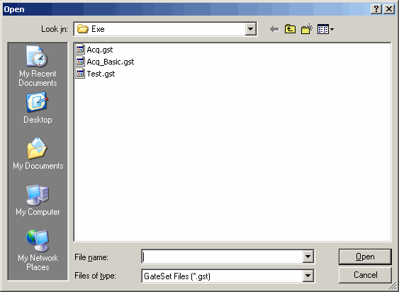
File - Open GateSet File
      The 'Open GateSet File' dialog is used to load a new
      GateSet definition file:
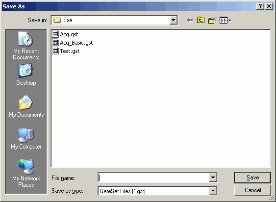
File - Save GateSet File
      The 'Save GateSet File' dialog is used to save the current
      GateSet definition file for future use.

      Note:
           The current contents of the GateSet Editor window will
           be saved as file Acq.gst when the ACQ program is
           terminated and reloaded when the program is restarted.
Test GateSet(s)
      The 'Test GateSet(s)' option processes the current contents
      of the editor checking for simple syntax and parameter errors.
      As an example, if the following GateSet is tested

         E
         C 3, P 2
         F 1, S /MCS Spectrum/, B (2, /PHS Spectrum/)
         F 3, S /PHS Spectrum/

      an error message will be shown:
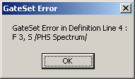
      The message simply shows the GateSet line where the
      'F 3' is the error. The number of parameters was set to 2.

         The ACQ Data Selection Spectrum dropdown box will also
      be updated to reflect any enabled, disabled, added, or
      removed gateset spectrum names.

         Also note that the specification of a spectrum in a
      B[ounds] statement that is not built with a corresponding
      F[or]/S[pectrum] statement acts as if NO B[ounds] statement
      was specified. (ie the bounds will be from 1 to 8192)
Help
         Clicking on the 'Help' option opens the Documentation Help
      screen at the 'GateSet Definition Editor' for quick access to the
      command syntax.

Scanned Device Information
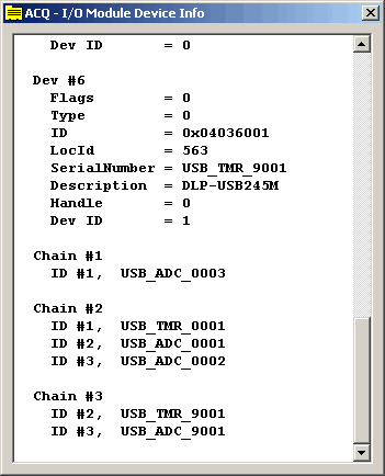
         Clicking on the 'Scanned Device Information' menu item
      displays the information about the scanned IO modules:
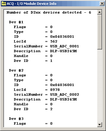
         The information is read from the USB device driver and
      from the USB IO Module during program initialization.

         Scrolling to the end of the information also shows the
      'Chain' sequence for the detected IO modules.

DDE Link
         Clicking the 'DDE Link' menu item shows the
      DDE Link options:
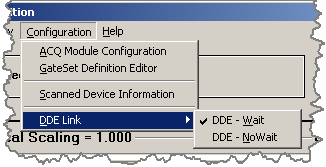
         The DDE (Dynamic Data Exchange) Interface can be
      configured to:

            1)  Execute the Advisory and
                return at completion  (DDE-Wait)  or

            2)  Schedule the Advisory and
                return immediately  (DDE-NoWait)


         Method 1 is the default and recommended
      proceedure if the Advisory command requires more
      than a few seconds to complete.  This ensures that
      the calling program will wait for the completion
      of the Advisory Command.

         If the Advisory takes a very long time,
      i.e. greater than 60 seconds,  then be sure to
      explicitly set the LinkExecuteTimeout value greater
      than the longest Advisory execution time.


      The DDE interface parameters are:

          Program Name:     ACQ
            Link Topic:     AcqF
              Count Rate:   TbxCntRate
              Time:         TbxTime

         Advisory commands can be sent to ACQ by the
      Link Topic AcqF using the following syntax:

              Advisor = #

      where # is        1    Start Acquisition
                        2    Stop  Acquisition
                        7    New File
                        8    Save Data
                        9    Wait

         Refer to the Execute Advisory menu descriptions
      for an explanation of each operation.


