ACQ - Hardware
         The acquisition program supports I/O modules with
      specific characteristics:

          1.  The device control register is 8-bits with
              the lower 4-bits having common functionality
              to enable/disable acquisiition, set the acquisition
              mode to single/multiparameter, and initiate
              a 'Test' USB data transfer cycle.

          2.  The device data register is 16-bits with
              the lower 13-bits the acquisition data and
              the top 3-bits the physicsl ID of the I/O module.

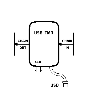
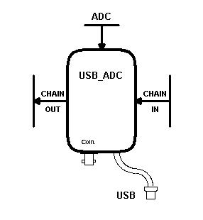
      Currently two I/O modules are supported by the acquisition
      program:  The USB_ADC and USB_TMR modules.  Usually each
      I/O module has an input plug on the right side and an
      output socket on the left side.  The input plug allows
      jumpering of the ID bits to change the default ID of a
      single I/O module or the default starting ID of chained
      I/O modules.  These I/O devices will be depicted as shown in
      the following drawings for the USB_TMR and USB_ADC modules:


-
Acquisition Hardware Configuration

Independent I/O Modules
         The basic acquisition configuration is the single
      (independent) I/O module.  A single I/O module is configured
      as a 1 element chain.  Multiple independent I/O modules
      are each configured as 1 element chains.  The physical
      ID of the I/O module can be set by jumpering the input
      ID bits.  The default physical ID is 0, this corresponds
      to an instrument ID of 1 in the acquisition program.

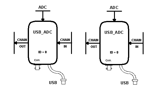
          A typical independent I/O module configuration is
      shown with two USB_ADC modules.  Each module has the
      same ID (=0).  However, the acquisition program will
      will assign each module to seperate 1 element chains.


Chained I/O Modules
         A string of daisy-chained I/O modules, not to exceed
      8 I/O modules, is configured as a multi-element chain.
      The physical I/O module's ID is determined by its
      location in the chain.  The first I/O module in the
      chain must have the lowest ID number within the chain
      (required by the acquisition program).  The actual ID
      of the first I/O module can be set by jumpering the
      input ID bits (as shown on the I/O module).  Each
      subsequent I/O module then has an ID one higher than
      its predecessor.  The default physical ID of the first
      I/O module is 0, this corresponds to an instrument ID
      of 1 in the acquisition program.

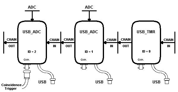
          A typical chained I/O module configuration is shown
      with a USB_TMR and two USB_ADC modules.  The module
      physical IDs will be, from right to left, 0 for the
      USB_TMR and then 1 and 2 for the following USB_ADC
      modules.  A single 'coincidence trigger' signal is
      required if two or more of the I/O modules are to be
      operated in the multiparameter acquisition mode.  The
      trigger signal is passed through the 'chain' and
      synchronizes each participating I/O module to acquire
      data simultaneously.


