The TransImpedance Amplifier Module
The TransImpedance Amplifier Module
The TransImpedance Amplifier converts the photogenerated
current from a photodiode into a voltage. A simplifed
drawing of the TransImpedance Amplifier helps explain
the inner workings of the module.
 The total gain of the amplifier is the product of the
transimpedance amplifier, stage 1, stage 2, gain potentiometer,
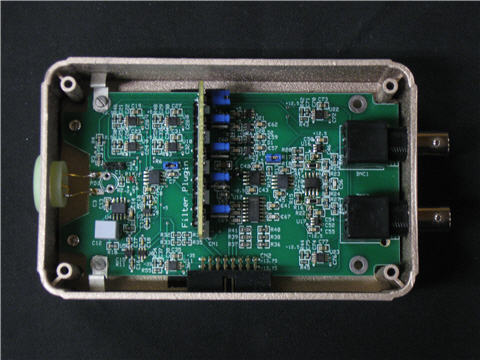
stage 3, and output driver gains. Stages 1 and 2 on the main
amplifier board and stage 3 on the filter plugin have jumpers which
may be removed to give a gain of 1 rather than the default of 10.
The jumper positions, photdiode pads, output BNC connectors,
and interface connector are shown here:
The total gain of the amplifier is the product of the
transimpedance amplifier, stage 1, stage 2, gain potentiometer,
stage 3, and output driver gains. Stages 1 and 2 on the main
amplifier board and stage 3 on the filter plugin have jumpers which
may be removed to give a gain of 1 rather than the default of 10.
The jumper positions, photdiode pads, output BNC connectors,
and interface connector are shown here:
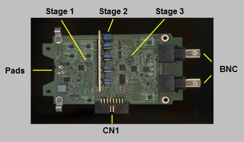 The output driver has differential BNC outputs with an output
impedance of 50 ohms giving a gain of 1 into 50 ohm loads.
The output stage is stable without a load giving a gain of 2.
The 'Pads' show where the photodiode is connected to the
amplifier. CN1 provides the power connections and the
interface connections to control the gain potentiometer, and
read the photodiode current and the signal+noise level.
When the internal Signal+Noise level approaches 1 volt or
larger then it may be advantageous to reduce the overall
gain of the amplifier module. In this case change the
gain by removing the stage 3 jumper first then if required
remove the stage 2 jumper and lastly the stage 1 jumper.
Note that changing the internal gain jumpers requires that
the setup configuration file for the TiaCtrl program must
be changed to match the physical configuration of the amplifier.
The default file is ...\TiaCtrl\TiaCtrlCfg\TiaCtrl.stp:
// TiaCtrl Setup File
[TiaCtrl]
// port# Serial Number
// ----- -------------
Usb = 0, PDIO-01
//
// Input Current Offset
// --------------------
uA = 0.010
//
// Signal+Noise Offset
// -------------------
Volts = 0.000
//
// Stage Gains
// -----------
Tia = 1.E06
1st = 10
2nd = 10
3rd = 10
Thus make the required changes for the '1st', '2nd', and '3rd'
entries in the file and save.
When more than one TIA unit is to be controlled
the TiaCtrl.stp file will contain multiple [TiaCtrl]
entries, one for each TIA unit.
The output driver has differential BNC outputs with an output
impedance of 50 ohms giving a gain of 1 into 50 ohm loads.
The output stage is stable without a load giving a gain of 2.
The 'Pads' show where the photodiode is connected to the
amplifier. CN1 provides the power connections and the
interface connections to control the gain potentiometer, and
read the photodiode current and the signal+noise level.
When the internal Signal+Noise level approaches 1 volt or
larger then it may be advantageous to reduce the overall
gain of the amplifier module. In this case change the
gain by removing the stage 3 jumper first then if required
remove the stage 2 jumper and lastly the stage 1 jumper.
Note that changing the internal gain jumpers requires that
the setup configuration file for the TiaCtrl program must
be changed to match the physical configuration of the amplifier.
The default file is ...\TiaCtrl\TiaCtrlCfg\TiaCtrl.stp:
// TiaCtrl Setup File
[TiaCtrl]
// port# Serial Number
// ----- -------------
Usb = 0, PDIO-01
//
// Input Current Offset
// --------------------
uA = 0.010
//
// Signal+Noise Offset
// -------------------
Volts = 0.000
//
// Stage Gains
// -----------
Tia = 1.E06
1st = 10
2nd = 10
3rd = 10
Thus make the required changes for the '1st', '2nd', and '3rd'
entries in the file and save.
When more than one TIA unit is to be controlled
the TiaCtrl.stp file will contain multiple [TiaCtrl]
entries, one for each TIA unit.
      The Amplifier Module design details, including schematics,
    printed circuit board layouts, and parts data sheets are
    available in the following PDF file:

          Amplifier Module Documentation


Last Updated: March 2025